About the defects and improvement methods in the process development of ductile iron parts
- Share
- publisher
- Lisa
- Issue Time
- May 15,2020
Summary
Yinxiao Machinery’s engineers recorded the defects in the casting process of thick ductile iron castings and proposed corresponding solutions.


About the defects and improvement methods in the process development of ductile iron parts
In June 2020, we helped Chinese customers develop and research a ductile iron casting. Our engineers sorted out and recorded the problems that occurred during the development process, as well as his records and improvements.
Summary:
Based on past experience, a similar process plan for mature parts was adopted, and solidification simulation was performed on the process of newly joined castings. The simulation results show that this kind of similar scheme makes the castings directly below the sprue or the castings directly below the outgassing and feeding riser, there may be a certain probability of shrinkage porosity. However, considering the experience gained and the characteristics of graphitization expansion of ductile iron material itself, it is believed that the probability of shrinkage porosity in castings should not be very high.
However, as a precaution, an alternative plan for cold iron was prepared in advance, which means that once the test is unsuccessful, the second set of cold iron feeding plans will be launched to ensure the compactness of the internal organization. After a round of successive tests of large parts A and small parts C, it was found that the original similar schemes could not achieve perfect application on these types of castings. After comparison and analysis, the smallest casting C was improved first, and the result was a perfect success, so the experience was copied on the other two castings, and the result was a final word.
At the same time, a similar process improvement was adopted on an old product casting, and the perfect result was also achieved. It can be concluded that the full use of the independent hot pouring riser, the thick and large wall thickness of the ductile iron parts to facilitate the realization of sequential solidification and the full use of the characteristics of graphitization expansion, to obtain a sound casting without shrinkage and porosity. One of the important ideas of iron casting process design.
Preface
The characteristic of the moulding process we choose for our customers is the use of coated sand hot box shell mold cores to make the shell and to form the shell, and use steel shots for pouring. When three types of ductile iron parts with similar structures (see Casting A with a pre-cast riser in Figure 1) were received, it was found that their structure and shape were similar to a variety produced by the company (see Figure 2 with a pre-cast riser. Mature similar parts) are very similar, so in order to avoid detours, the existing process plan is directly used for reference and solidification simulation is performed at the same time.
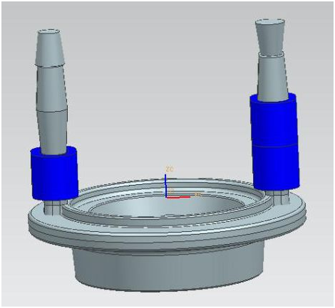
Figure 1 Casting A with preset pouring riser
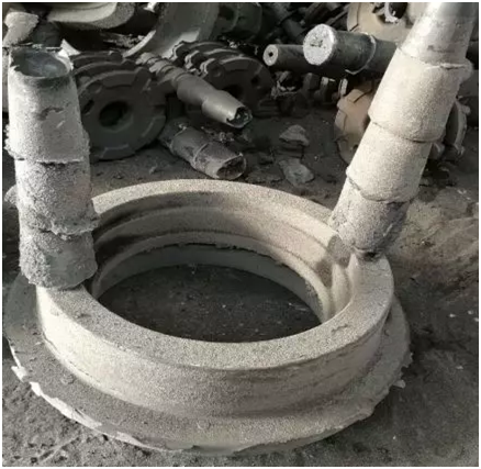
Figure 2 Mature parts with pouring riser
The simulation results (see Figure 3, the results and analysis of the solidification simulation of the precast riser casting A) show that although there is a local shrinkage porosity, according to past experience-for example, similar parts also have shrinkage porosity during simulation but actual castings It did not happen-I think it should and will not have shrinkage, and at the same time increase the riser to improve the feeding capacity of the riser. So the first round of tests was carried out on the large casting A.
The test casting found slight shrinkage porosity after sectioning (see Figure 4, there is a slight shrinkage porosity state after sectioning of casting A), and the hotter the riser, the more serious the shrinkage porosity, the colder the riser, the slighter or even complete No. For casting B (the shape is exactly the same as casting A, but the size of each size is smaller, the weight is lighter, the parameters of the initial design of the pouring riser are exactly the same, and casting B is not shown here). The test results are the same as casting A.
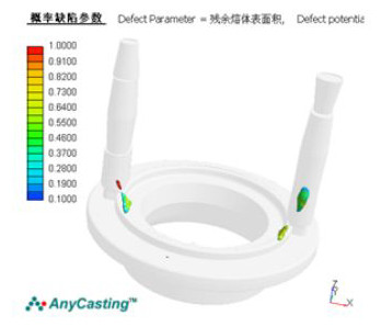
Shrinkage defect prediction
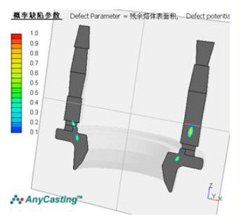
Shrinkage defect prediction (section diagram)
The figure shows the result of shrinkage defect prediction, and the right figure is a cross-sectional view. Compared with the placement direction of castings, the placement of this plan is more reasonable, and it is recommended to use this plan. At the same time, there is an isolated liquid phase during the solidification of the casting, but the area is small. In addition to the self-feeding of the casting, the probability of shrinkage defects is small and can be ignored.
Figure 3 Solidification simulation results and analysis of casting A with pre-cast riser
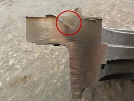
Figure 4 There is a slight shrinkage porosity after casting A is cut
The same test was then carried out on the smallest type of casting C, and the cut results were similar, that is, the inside of the castings with cold risers and no risers were very dense, while the inside of the castings directly below the hot risers had shrinkage. Loose (see Figure 5, there is a slight shrinkage porosity inside the hot riser of casting C after sectioning).
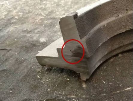
Figure 5 There is a slight shrinkage porosity inside the casting C hot riser after sectioning
And this is only below the hot riser, and the volume range of shrinkage porosity is very small, which is obviously smaller than that of A and B, and such shrinkage porosity is not enough to affect the use function of the casting. For this reason, the idea was changed, which is to make full use of the self-feeding ability of thick castings, abandon all cold risers, and use independent hot pouring risers for testing. Afterwards, it was first tested on the casting C and succeeded (Figure 6 shows the state of the independent hot pouring riser casting C to be poured with the sand mold after the improvement). The same idea was implemented on casting A and casting B, and the same effect was achieved (Figure 7 shows the state of independent hot pouring riser casting A waiting for sand casting after improvement). In the end, the three castings were successfully developed and delivered, and the second set of alternative plans was not implemented.
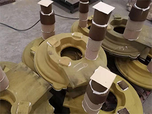
Figure 6 The state of the improved independent hot pouring riser casting C ready for pouring sand
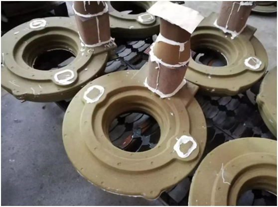
Figure 7 The state of the improved independent hot pouring riser casting A to be poured
Analysis of the reasons for the failure of the first round of trials
The basic information of the three casting sizes and the pouring riser during the first round of testing are shown in the following table
Material | Max size of finished product (mm) | Casting (blanket) net weight KG |
Maximum thermal pitch mm
|
Heat riser neck size mm
|
Total weight of riser KG
|
Pouring riser layout | Is the upper box surface bulging? | Density of castings | |
|
Casting A
|
QT400-18LT | Φ560x168 | 80.5 |
about Φ58
|
60x40
|
23.5
|
A pouring a risk | Press three pieces of box iron. The bulge from the side of the upper box riser to the first step is severe | There is shrinkage just below the neck of the hot riser, slight or no shrinkage in the cold riser, and no shrinkage in the area without riser. |
|
Casting B
|
QT400-18LT | Φ510x146 | 64.1 |
about Φ48
|
60x40
|
23.5
|
|||
|
Casting C
|
QT400-18LT | Φ500x138 | 47.2 |
about Φ45 |
50x30
|
22
|
After pressing three pieces of box iron, no obvious bulging was found | ||
Mature casting | QT450- 10 | Φ480x155 | 64.5 | about Φ45 | 50x30 | 22 | Dense inside casting | ||
Remarks | Due to the use of coated sand hot core box shell mold cores to make the shell and form the shell, the specifications of the riser are relatively unified, and the above are all in one form. | ||||||||
It is not difficult to see from the above various information that the main reason for the failure of the first test should be attributed to the small neck of the heat riser and the small volume of the heat riser, so there is shrinkage under the heat riser. And why does the cold riser sometimes have shrinkage? Because the cold riser also has similar characteristics to the hot riser, more molten iron passes through here, thus overheating the sand shell, causing the molten iron to dissipate slowly and finally solidify, and no effective liquid iron can be obtained. supplement. And because the cold riser neck is the same as the hot riser neck, the riser neck cannot be closed in time, and the expansion of graphite cannot be effectively used to realize self-feeding. Although this cold riser and riser neck played a better role in exhausting and collecting slag, because of the unreasonable size, it seriously interfered with the solidification order of the temperature distribution field, so shrinkage occurred.
So why didn't the similar problems occur in the referenced mature parts? Through careful inspection and comparison of the drawings, it is found that the structure looks similar, but in fact there are still certain differences, such as the difference in wall thickness between adjacent walls, and the feed channel from the contact point of the riser and the casting to the distal end. In particular, there is a significant difference between the positions of castings A and B where the riser is placed and the casting C and mature parts, while the casting C and mature parts are highly consistent. Therefore, the results of casting B and casting A are similar, and casting C is significantly better than A and B. Casting C still has a certain degree of shrinkage, probably because the difference in material and the suitability of the pressure box iron have played a major role.
In addition to the above differences, in addition to blindly duplicating the process, and overly trusting experience and negating the risk of the solidification simulation results, there are also small differences in the material of the castings, swelling caused by insufficient weight of the on-site pressure box, etc. The combined effect of these factors will inevitably cause the occurrence of the defects. If shrinkage does not occur during the test, it will be an accident, which will bring greater risks to subsequent mass production.
The reasons for casting shrinkage near the riser neck are nothing more than:
①. Low carbon equivalent of molten metal;
②. Low riser temperature, early solidification and poor feeding effect;
③. The location or size of the riser is unreasonable, and the volume shrinks during the solidification process of the molten iron and cannot be compensated for volume loss. The volume loss is concentrated in one place to form shrinkage cavities, and shrinkage porosity is dispersed and distributed locally;
④ The shape or cross-sectional area of the riser neck is unreasonable, and the feeding channel is blocked, so that the riser fails to play a feeding role.
It can be seen that the shrinkage porosity of the casting near the riser neck is also in line with the above points.
Basic measures and results to prevent shrinkage porosity of castings at the riser
According to the basic countermeasures to solve the riser neck shrinkage, including:
①. Change the position or shape of the riser, and change the solidification sequence so that the shrinkage parts that cannot be compensated can be compensated, and shrinkage or shrinkage can be eliminated.
②Place the cold iron in the proper position.
③Change the position of the inner gate to obtain a reasonable temperature field and solidification sequence.
④ Increase the volume of the riser.
⑤Enlarge (or reduce) the riser neck.
⑥Using the integrated method of pouring and riser to increase the temperature of the riser.
At the same time, in combination with the above analysis, it was decided to immediately conduct another test on C in good condition. It is to use an independent pouring riser as shown in Figure 6. The heat riser neck and the parameters of the heat riser remain unchanged, the outlet riser is cancelled, and the original pressure box The iron is increased from 3 to 5 pieces (each piece weighs 30Kg) to continue to maintain sufficient stiffness of the sand mold, while increasing the carbon of the original molten iron by 0.1%, and the silicon of the original molten iron continues to maintain a low value (keep the impact value low). The result of the test is that the casting has no pores due to the independent pouring riser, and there is no small shrinkage porosity in the casting; the body structure of the section without the riser is also dense, so the scheme is completely effective.
On this basis, a similar scheme was adopted for castings A and B, that is, the hot riser and the riser neck were increased respectively, and the molten iron entry position was changed due to the increase of these parameters, the original cold riser was cancelled, and the pressure box iron Increased from the original 3 to 7. The other measures were the same as those in C. As a result, the original problems of A and B disappeared, and the shrinkage was resolved. Subsequent mass production also fully confirmed all the above-mentioned analyses and the effective measures taken. See the table below for some specific parameters after the change:
Material | Max size of finished product (mm) | Casting (blanket) net weight KG | Heat riser neck size mm | Total weight of riser KG |
Pouring riser layout
|
Is the upper box surface bulging?
|
Density of castings
|
|
|
casting A
|
QT400-18LT | Φ560x168 | 80.5 | 70x60 | 25 |
One-shot riser
|
Press seven pieces of box iron
|
No shrinkage
|
|
casting B
|
QT400-18LT | Φ510x146 | 64.1 | 70x60 | 25 |
|||
|
casting C
|
QT400-18LT | Φ560x138 | 47.2 | 45x28 | 14 |
Press five pieces of box iron
|
Promotion and application of similar experience
Based on the above-mentioned experience, infer other things, another casting (net weight 156Kg) was quickly improved. Figures 8 and 9 below show the original process of this casting, using independent hot pouring risers, sand molds with vent holes, and casting caps. The contrast of the casting state of the mouth. The results of the test are very good results and very good economic benefits. The production rate of this piece of technology has increased by 12% compared with the original technology, and the shrinkage and waste rate after processing has been reduced from 20% to 0.
It can be seen that, making full use of the independent hot pouring riser, making full use of the thick and large wall thickness of ductile iron parts to facilitate sequential solidification and making full use of the characteristics of graphitization expansion to obtain a sound casting without shrinkage. It is ductile iron. One of the important ideas of casting process design.
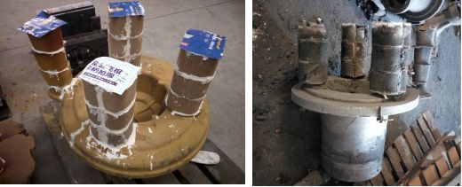
Figure 8 The original process sand mold and the casting state of the riser to be poured
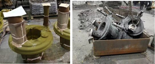
Figure 9 Castings with independent hot pouring risers, sand molds with vent holes and castings with pouring risers